Blog
Top 10 Ball End Mills for CNC Machining Buyers Guide
Ball-nose cutters can leave a smooth sculpted surface—or a costly pattern of ridges. The difference often starts with tool selection. This guide compares ten options for CNC buyers, from general-purpose carbide cutters to specialized designs for finishing, hardened materials, and tight-radius details. It focuses on practical factors: flute count, coating, substrate, reach, shank size, and workpiece geometry.
A Ball End End Mill is not automatically the best choice for every curved feature. Its rounded tip suits contours, molds, and three-dimensional surfaces, but stepover and toolpath strategy shape the final finish. A long-reach cutter may access a deep pocket, yet deflection can become a problem. Small details matter. So does machine rigidity.
A useful shop-floor principle is: “Match the cutter to the surface, setup, and finish target.” I cannot responsibly attribute that wording to a named industry expert without a verifiable source. That gap is worth acknowledging; buying guides can blur opinion and evidence. Here, comparisons should be checked against manufacturer specifications and tested conditions, not just catalog claims. Use this overview to narrow the field, then confirm diameter, corner geometry, runout, and cutting data for your machine and material. The right tool is rarely the one with the longest feature list. It is the one that performs predictably in your setup. Sometimes, a careful test cut tells you more than a brochure. That is the honest starting point.
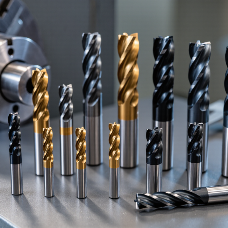
What Ball End Mills Are and How Their Geometry Works
A ball end mill has a rounded, hemispherical tip, with a radius equal to half its cutting diameter. This shape lets it follow curved surfaces and machine smooth 3D contours. At the exact center of the tip, cutting speed approaches zero. That matters.
The flutes spiral along the tool and carry chips away from the cut. Their number and shape affect chip space, cutting action, and finish. During a shallow pass, only a small band of the rounded edge may engage the material. A larger stepover leaves taller scallops; reducing it usually makes the surface smoother, but adds machining time.
Toolpath direction also changes where the ball contacts the workpiece. On a steep wall, contact shifts toward the side of the tip, where cutting speed is higher. Near a flat surface, contact moves closer to the center, which can encourage rubbing and heat. In shop practice, a faint rough patch is not always a dull tool. Feed, stepdown, tool deflection, and setup stiffness deserve a check too. Geometry explains much, but not everything.
Key Specifications for Comparing Ball End Mills
A ball end mill’s diameter and ball radius determine the smallest curve it can cut. Match these dimensions to the part’s tightest feature, then check the cutting length. Excessive reach can increase deflection, leaving chatter marks on a curved surface. Small details matter.
Tips: Compare flute count, helix angle, and substrate with your material. Two flutes can leave more room for chips in softer materials, while other setups may benefit from extra cutting edges. Check the shank diameter and total length against your holder and tool clearance. A quick fit check can prevent an avoidable setup change.
Coating choice should suit the workpiece and cutting conditions, not just the tool’s advertised range. Review the recommended speed and feed, and confirm the machine can hold the required runout. Even a suitable cutter may perform poorly if it is held off-center. I would also inspect the ball nose under magnification after a short trial cut; wear can be hard to spot by eye. Specifications narrow the options, but a controlled test in the actual material remains useful.
Top 10 Ball End Mills for CNC Machining Buyers Guide - Key Specifications for Comparing Ball End Mills
Compare ten common metric ball-end mill diameters and their corresponding ball radii. Radius is half the nominal diameter; these sizes are shown for reference, not as a product ranking.
When comparing tools, also check flute count, overall length, cutting length, shank diameter, substrate, coating, and the manufacturer’s recommended cutting conditions. Availability and specifications vary by tool series.
How to Evaluate the Top 10 Ball End Mills for CNC Machining
To evaluate the top 10 ball end mills, compare them under identical cutting conditions, not from catalog claims alone. ISO 8688-2:1989 describes controlled tool-life testing for end milling; its core lesson is consistency. Hold the workpiece alloy, toolpath, stickout, coolant, and spindle speed constant. Record cutting time, flank wear, surface finish, and edge chipping. Small differences matter.
Run three repeated cuts per tool as a practical screening test. Log the results, including failures. A cutter that lasts longer but leaves visible scallops may cost more in finishing time. Check ball radius, flute count, coating, shank runout, and recommended engagement against the actual job. ISO 13399 provides a standardized framework for cutting-tool data, helping buyers compare specifications without relying on marketing language. Still, published values cannot fully predict performance in a rigid or flexible setup.
That part is easy to underestimate. A modest test cut in the real material can reveal chatter, burrs, or poor chip evacuation before a full production run.
Choosing a Ball End Mill for Materials and Machining Tasks
A ball end mill’s radius, flute design, and cutting length should match both the material and the feature. For 3D contours in aluminum, a sharper edge and open flute space can help clear chips and reduce smearing. In hardened steel, a rigid setup and conservative engagement matter more; heat and tool deflection can quickly spoil a finish. For a tight cavity, check the tool’s reach before choosing a longer cutter. Extra length may seem convenient, but it can increase vibration. Small details matter. Match the stepover to the finish requirement, then verify the toolpath and spindle limits. A test cut is worth the time, even when the setup seems obvious.
Tips: Inspect the tool for edge wear, and check runout with a suitable gauge. Keep chips moving with effective coolant or air, as the material and machine allow. Listen for chatter; a sharp, steady sound is useful, but not a substitute for inspecting the cut. Record feed, speed, and stepover after a successful test. These notes may need adjustment on the next setup.
Top 10 Ball End Mills for CNC Machining Buyers Guide - Choosing a Ball End Mill for Materials and Machining Tasks
| Rank | Ball End Mill Configuration | Typical Construction | Suitable Materials | Best-Fit Machining Tasks | Selection Considerations |
|---|---|---|---|---|---|
| 1 | Two-flute ball end mill for aluminum | Solid carbide; polished flutes; commonly uncoated or supplied with a coating intended for nonferrous metals | Aluminum alloys and other nonferrous metals | 3D contouring, slots, and pocket details where chip evacuation matters | The larger flute space helps clear chips. Use sharp edges and suitable coolant or air delivery to reduce built-up edge. |
| 2 | Three-flute ball end mill for aluminum | Solid carbide; polished cutting edges and flutes | Aluminum alloys and some plastics | Finishing contours and general 3D milling when a balance of chip space and edge support is needed | Check the tool maker's guidance for the specific material and machine. Avoid allowing chips to recut in deep features. |
| 3 | Four-flute ball end mill for general steel machining | Solid carbide or high-speed steel; often supplied with a coating selected for steel cutting | Low- and medium-carbon steels and some alloy steels | Profile finishing, curved surfaces, and general-purpose 3D machining | More flutes can support the cutting edge but leave less room for chips. Match flute count to chip load, engagement, and coolant access. |
| 4 | Ball end mill for stainless steel | Solid carbide; geometry and coating selected for heat resistance and controlled cutting | Austenitic and other machinable stainless steels | Contouring and finishing with stable tool engagement | Stainless steel can work-harden. Use a consistent feed and avoid dwelling or rubbing; follow material-specific cutting data. |
| 5 | Ball end mill for hardened steel | Solid carbide; hard-material geometry, often with a heat-resistant coating | Hardened tool steels and other heat-treated steels within the tool's rated hardness range | Finishing dies, molds, and hardened 3D contours | Confirm the tool's hardness rating. A rigid setup, controlled engagement, and suitable toolpath are important for tool life. |
| 6 | High-flute-count finishing ball end mill | Solid carbide; typically four or more flutes, depending on diameter and design | Steels and other materials specified by the tool maker | Fine 3D finishing and reduced scallop height on contoured surfaces | Use when the machine and setup can maintain the required feed. Fewer flutes may be preferable when chip evacuation is limited. |
| 7 | Micro ball end mill | Small-diameter solid carbide with a precision-ground ball nose | Small features in plastics, nonferrous metals, and steels appropriate to the tool specification | Engraved details, miniature features, and small-radius 3D contours | Small tools are sensitive to runout, tool deflection, and chip load. Use a suitable high-speed spindle and a rigid, low-runout holder. |
| 8 | Long-reach ball end mill | Solid carbide cutting end with extended reach; some designs use a reduced neck | Materials compatible with the tool's cutting geometry and substrate | Deep cavities and contours with restricted access | Longer reach increases deflection risk. Choose the shortest reach that clears the part and reduce cutting forces where necessary. |
| 9 | Tapered ball end mill | Solid carbide; tapered shank or neck with a ball-shaped cutting end | Mold steels, graphite, and other materials specified for the tool | Deep, narrow cavities and 3D features requiring added stiffness compared with a similar slender straight tool | Check taper angle, ball radius, and neck clearance against the part geometry and toolpath requirements. |
| 10 | High-speed steel ball end mill | High-speed steel, typically available in common flute counts and diameters | Aluminum, plastics, and softer steels within the tool's operating limits | General contouring on machines where lower cutting speeds or greater tool toughness are useful | Usually suited to lower cutting speeds than solid carbide. Verify the material, machine, and tool maker's recommended parameters. |
Buying note: These are general tool-selection categories, not a universal performance ranking. Confirm ball radius, diameter, flute length, reach, substrate, coating, and cutting data with the tool maker for the workpiece material, machine, holder, and toolpath.
Buying, Using, and Maintaining Ball End Mills
Choosing a ball end mill starts with the material and the shape of the part. A smaller diameter can reach tight curves, but it bends more easily and may chatter. Match flute count and tool material to the workpiece, then check the tool’s reach against the pocket depth. Long reach reduces rigidity. Not ideal. A coating may help with heat or wear, but it cannot correct poor chip evacuation or excessive runout. Compare the tool’s recommended cutting data with your machine’s actual rigidity and spindle limits.
During setup, keep the tool and holder clean, and check runout before cutting. Even slight runout can make one cutting edge carry too much load. Use CAM settings that suit the geometry: stepover affects surface scallops, while feed and engagement affect cutting forces. For a curved surface, a small test pass can reveal tool marks before they spread across the whole part. Coolant or air blast should clear chips rather than push them back into the cut. No single setting fits every machine.
After machining, wipe the tool clean and inspect its cutting edges under good light. Look for chipped corners, uneven wear, or built-up material. Store tools separately so their edges do not knock against other cutters. A worn tool may sometimes be reground, but the new diameter and profile must still suit the job. Regrinding is not always worthwhile. Keep simple notes on tool life, material, and cutting conditions; they can guide the next setup, though one successful run is not a guarantee.
Article Source:
Exclusive Access
Unlimited Resources
Detailed information on our products to assist you with the planning of your cable management project
Register Now