Blog
How to Choose a Machine Vision Telecentric Lens
Choosing a machine vision telecentric lens requires more than matching a camera mount. The lens must suit the inspection task, object size, sensor, and lighting environment. A small mismatch can produce inaccurate edge measurements, even when the image appears sharp.
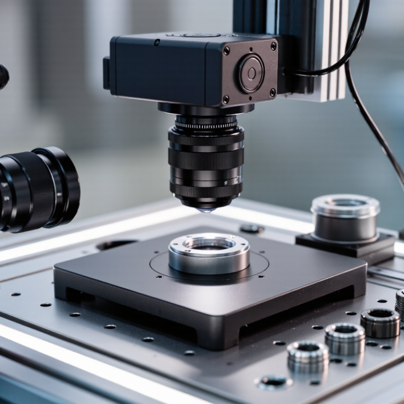
In practical inspection systems, I begin with the required field of view and measurement tolerance. Then, I compare magnification, working distance, depth of field, and sensor coverage. A telecentric lens helps maintain consistent object size when parts shift along the optical axis. This benefit is valuable for checking molded components, metal washers, connectors, and machined edges. However, telecentric performance does not remove every optical limitation. Lighting, vibration, surface reflections, and poor fixturing still affect results. The lens cannot repair an unstable setup.
Look closely at the specifications. Confirm whether the design is object-space, image-space, or bi-telecentric. Check the usable image circle before selecting a camera. Review distortion data, aperture range, mounting threads, and working distance tolerances. I also recommend testing the actual part, not only a calibration target. Real surfaces often reveal glare, burrs, and shadows that laboratory charts hide.
No lens is universally perfect. A longer working distance may simplify lighting but increase system cost. A wider aperture may improve brightness but reduce depth of field. These trade-offs deserve honest evaluation. Reliable selection combines manufacturer data, application experience, repeatability tests, and documented measurement results. When uncertainty remains, request sample images and test several lens settings before approving the final machine vision telecentric lens. Small errors become expensive when repeated thousands of times.
Define Inspection Accuracy: Target <0.1% Distortion for Metrology
How to Choose a Machine Vision Telecentric Lens
In metrology, lens choice starts with a measurable distortion limit, not a catalog image. For inspections requiring tight tolerances, set a target below 0.1% distortion. That figure means a 100 mm feature may shift by less than 0.1 mm across the measured field. Telecentric optics help maintain stable magnification when parts move slightly along the optical axis. This reduces edge enlargement and makes dimensional results more repeatable.
Repeatability matters.
Match the lens to the sensor size, pixel pitch, field of view, and working distance. A large field may demand lower magnification, but excessive reduction can waste pixels on critical edges.
Check the clear aperture against the part, especially when shafts, holes, or raised surfaces block light. Use coaxial or diffuse illumination when shiny metal creates false contours.
Do not judge distortion from one image. Capture a calibrated grid across the entire inspection area. Measure residual error at the center, corners, and intermediate points. Record temperature and mounting orientation, since small changes can affect results.
In practice, a lens rated below 0.1% may still fail if calibration is weak or the fixture flexes. I have seen accurate optics produce inconsistent measurements after a loose mount shifted by a fraction of a millimeter. That lesson is easy to overlook. Verify performance with certified artifacts, repeated runs, and independent dimensional checks. Keep raw images and calibration records; they make troubleshooting less subjective. A careful selection leaves enough resolution for the smallest tolerance, not merely the largest part.
Match Magnification and Sensor Format: From 1/1.8″ to 4/3″ Systems
How to Choose a Machine Vision Telecentric Lens
Magnification must match both the object field and sensor format. The calculation is simple: magnification equals sensor width divided by the required field width. A 1/1.8″ sensor is approximately 7.1 mm wide. At 0.1× magnification, it captures about 71 mm horizontally. A 4/3″ sensor is approximately 17.3 mm wide, covering about 173 mm at the same magnification. That difference is substantial.
Sensor format also affects lens coverage. A lens designed around a 1/1.8″ image circle may vignette on a 4/3″ sensor. The corners can darken. They may also lose measurement accuracy. EMVA 1288 measurement reports recommend comparing signal-to-noise ratio, dynamic range, and spatial resolution under defined conditions. These metrics matter when inspecting polished metal, dark plastic, or tiny edge defects.
In practice, I measure the largest part first, including fixture tolerance. Then I select a working distance that leaves room for lighting and cables. A common mistake is choosing magnification from pixel size alone. I have made that shortcut myself. It looked correct on paper, but the field width was too narrow. Check the sensor’s actual active area, not only its nominal format. Format labels are useful, but they are not perfectly standardized.
Verify Telecentricity: Keep Chief-Ray Angles Near 0° for Stable Sizing
How to Choose a Machine Vision Telecentric Lens
Verify telecentricity before judging resolution. A telecentric lens keeps chief-ray angles close to 0°, reducing perspective changes across depth. This matters when a metal washer moves several millimeters under the camera. With a 0.1° chief-ray angle, a 100 mm depth change can create about 0.175 mm of image displacement, using Δx ≈ Δz tan θ. That shift may become a false dimensional error.
Do not rely only on a sharp catalog image. Measure the same gauge at different heights. Record edge position, magnification, and illumination each time. The EMVA 1288 Release 4.0 framework stresses repeatable measurement conditions, including exposure and sensor response. ISO 5725-2 also distinguishes repeatability from reproducibility. Your lens may look stable in one setup but drift after refocusing, vibration, or temperature changes.
A practical target is a chief-ray angle below 0.1° for demanding sizing tasks, though the correct limit depends on tolerance. Some applications need stricter control. Ask for measured telecentricity data, not only a nominal magnification value. Then test a certified reference object across the full working distance. I still see teams test at one height and approve the lens too quickly. That shortcut feels efficient, but it weakens confidence in every later measurement. Perfect 0° behavior is rarely practical. Stable, documented behavior is the real goal.
How to Choose a Machine Vision Telecentric Lens - Verify Telecentricity: Keep Chief-Ray Angles Near 0° for Stable Sizing
| Selection Dimension | Recommended Target or Data | Why It Matters | Verification Method |
|---|---|---|---|
| Chief-ray angle | Ideal value: 0°; select a lens with the lowest specified telecentricity error for dimensional inspection. | A near-zero chief-ray angle keeps object magnification substantially stable when the part moves slightly along the optical axis. | Move a calibrated target through the permitted working-distance range and compare measured dimensions. Reject setups showing unacceptable scale change. |
| Telecentricity type | Object-space telecentricity for stable part sizing; image-space telecentricity for stable sensor-side geometry; bilateral telecentricity when both are required. | The correct configuration depends on whether dimensional stability is needed on the object side, image side, or both. | Confirm the lens specification and test the complete camera-and-lens assembly rather than the lens alone. |
| Magnification | Common fixed magnifications include 0.5×, 1×, 2×, and 4×; choose the value that frames the feature with adequate margin. | Magnification determines field of view, object-side pixel size, and the required working distance. | Use: object-side field of view = sensor dimension ÷ magnification. |
| Field of view example | For a sensor width of 12.8 mm: 0.5× = 25.6 mm 1× = 12.8 mm 2× = 6.4 mm | The field of view must cover the complete inspection area, including positioning tolerance and edge clearance. | Measure the active sensor width and divide it by the selected magnification. Repeat for sensor height if needed. |
| Working distance | Use the lens’s specified working distance, commonly selected within approximately 50–200 mm for many industrial arrangements. | Working distance affects lighting access, mechanical clearance, fixture design, and the usable object-space telecentric region. | Check the mechanical drawing and verify that the entire part-height range remains inside the specified telecentric working range. |
| Distortion | For precision measurement, a common design target is less than 0.1%; tighter applications may require a lower value. | Low distortion reduces position-dependent measurement error across the field of view. | Image a calibrated grid or dot target and calculate the maximum deviation from the ideal geometric model. |
| Object-side pixel scale | With a 5 µm sensor pixel: 0.5× gives 10 µm per object pixel; 1× gives 5 µm; 2× gives 2.5 µm. | Pixel scale helps determine whether the smallest feature is adequately sampled by the camera. | Calculate: object pixel size = sensor pixel pitch ÷ magnification. Use multiple pixels across the feature for reliable measurement. |
| Sensor compatibility | The lens image circle must be at least as large as the camera sensor diagonal. A 1-inch-format sensor has a nominal diagonal of approximately 16 mm. | An undersized image circle causes corner darkening, loss of usable field, or vignetting. | Compare the lens image-circle specification with the actual sensor width, height, and diagonal. |
| Numerical aperture and f-number | Use the lens’s available aperture range; stopping down generally increases depth of field but reduces light reaching the sensor. | Aperture affects depth of field, diffraction, brightness, and the visibility of surface defects. | Test at several apertures while checking edge sharpness, contrast, exposure time, and the required measurement repeatability. |
| Resolution and MTF | Choose a lens whose specified MTF supports the camera pixel pitch and the smallest feature to be measured; avoid relying on megapixel count alone. | Insufficient optical resolution can blur edges and create unstable threshold locations even when the image appears sharp. | Inspect a high-contrast resolution target and compare edge-spread or MTF performance across the center and corners. |
| Depth of field | The usable depth of field is application-specific and decreases as magnification and aperture size increase. | Parts with height variation require sufficient focus tolerance without sacrificing dimensional accuracy. | Translate a calibrated step target through the object-space range and record the interval that meets the image-quality and measurement criteria. |
| Lighting compatibility | Use coaxial, diffuse dome, telecentric backlight, or other lighting suited to the feature geometry; backlighting is often preferred for silhouette measurement. | Telecentric optics stabilize geometry, but poor illumination can still produce weak, uneven, or ambiguous edges. | Evaluate contrast, glare, shadowing, and edge position under the actual production lighting arrangement. |
| Final acceptance check | Confirm magnification stability, distortion, repeatability, resolution, exposure, and mechanical clearance together. | A telecentric lens is part of a complete measurement system; camera, lighting, fixture, and software calibration all affect results. | Run a repeatability study using a traceable dimensional artifact across the full permitted part-position range. |
Select Working Distance and Aperture: Balance NA, DOF, and Light
Choosing a Machine Vision Telecentric Lens
Working distance should match the actual space around the inspected part, not only the catalog specification. Measure from the lens reference surface to the object plane. Leave room for fixtures, cables, and operator access. A longer working distance may improve access, but it can reduce available light and increase system size. I have seen small measurement errors create edge shadows near reflective metal parts.
Aperture controls the balance between numerical aperture, depth of field, and light. A wider aperture increases light and can reveal fine surface details. However, it usually reduces depth of field and makes height variation more visible. A smaller aperture extends depth of field, but the image becomes darker. Excessive stopping down may also introduce diffraction and soften tiny features. Real parts are rarely perfectly flat. That is the difficult part.
Tips: Set the working distance first, then test two aperture settings. Place a stepped target or spacer under the part. Check edge sharpness at the highest and lowest positions. If both edges remain clear, the depth of field is practical. If the image is too dark, improve illumination before opening the aperture too far. Coaxial lighting can help flat surfaces, while angled lighting may expose scratches. Record exposure, aperture, and working distance during testing. An initial estimate can fail. That is normal.
Check Optical Resolution: Sample Fine Details at Two Pixels per Feature
Choosing a machine vision telecentric lens starts with the smallest feature your inspection must resolve. A useful rule is to represent that feature with at least two sensor pixels. This is the minimum sampling point, not a guarantee of reliable inspection. Edges, lighting, contrast, and vibration can reduce usable detail.
For example, a 0.10 mm mark should cover at least two pixels after magnification. In demanding inspections, three or four pixels provide more stable measurements. Check the lens’s optical resolution across the entire image, not only at the center. A lens may show sharp edges in a test chart yet lose contrast near the corners. I have seen this mismatch create false rejects during production trials.
Tips: Calculate object-space pixel size before selecting the lens. Divide the sensor pixel pitch by the lens magnification. Then compare that value with the feature size. Test real parts with realistic lighting, exposure, and mounting conditions. Do not rely on a catalog resolution number alone. It can be incomplete. Also inspect dimensional distortion, working distance, and depth of field. A telecentric lens should preserve shape and size when part height changes slightly, but every setup has limits. Leave some resolution margin, because dust, focus drift, and imperfect alignment will eventually appear.
How to Choose a Machine Vision Telecentric Lens: Check Optical Resolution
For reliable sampling, a feature should cover at least two image pixels. The chart shows the theoretical minimum object-space feature size at different lens magnifications, calculated as: 2 × pixel pitch ÷ magnification.
Smaller pixel pitches and higher magnification reduce the minimum feature size that can be sampled. Actual usable resolution also depends on lens MTF, sensor performance, lighting, focus, and mechanical stability.
Article Source:
Exclusive Access
Unlimited Resources
Detailed information on our products to assist you with the planning of your cable management project
Register Now