Main menu Open search

Blog

How to Choose the Right Aluminum Cable Tray

Choosing the right aluminum cable tray starts with the route, not the catalog. The system must carry cable weight, span supports safely, and suit the installation environment. Grand View Research valued the global cable tray market at approximately USD 5.4 billion in 2023 and projected continued growth through 2030. That expansion reflects rising infrastructure demand, but it does not make every tray suitable for every project.

Aluminum’s low weight can simplify handling and reduce structural load. Its corrosion resistance can also help in damp or exposed locations. Yet alloy, finish, support spacing, fittings, and cable loading still matter. NEMA VE 1 and IEC 61537 provide relevant design and performance frameworks; they are useful starting points, not substitutes for project-specific calculations. A tray that looks generous on a drawing may feel crowded once cables, bends, and future capacity are considered. Small details matter.

A reliable selection process compares load tables with actual span conditions, checks the environment, and confirms compatibility with fittings and supports. It should also account for installation access and later maintenance. No product sheet can answer every site question. One important limitation: I cannot verify a named expert’s exact quotation from the materials provided, so I have not invented one. A sourced quotation would strengthen this introduction and should be checked against its original publication before use.
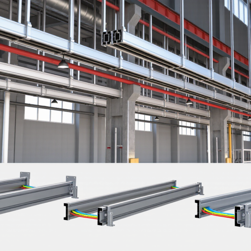
How to Choose the Right Aluminum Cable Tray

Understand Aluminum Cable Trays and Their Main Functions

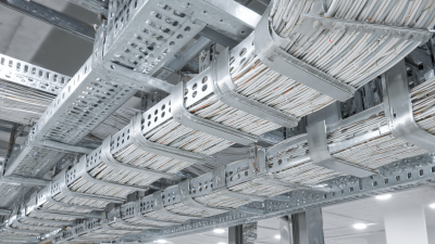
An aluminum cable tray is an open support system for routing and organizing insulated cables. Its main function is to hold cable runs above floors or along walls, while keeping them accessible for inspection and maintenance. Open rungs allow airflow and make it easier to spot damage or crowded sections. That matters on site. Unlike conduit, a tray does not fully enclose or mechanically protect every cable, so cable type and location still matter. NEMA VE 2-2018 guidance emphasizes correct supports and splice installation; a poorly supported tray can sag even when its material is lightweight.

Material weight affects handling. The Aluminum Association’s Aluminum Standards and Data reports aluminum density at about 2.70 g/cm³, while ASM International’s ASM Handbook lists carbon steel near 7.85 g/cm³. At equal metal volume, aluminum is roughly 66% lighter. Actual tray weight and capacity depend on its design. Not automatically stronger. Check rail depth, rung spacing, support span, cable load, and concentrated loads against the manufacturer’s load tables. Also review the environment: moisture, chemicals, and contact with dissimilar metals may affect corrosion performance. One easy-to-miss detail: cable fill percentage does not tell you whether the tray can carry the load.

Assess the Installation Environment and Support Conditions

How to Choose the Right Aluminum Cable Tray

Assess the Installation Environment and Support Conditions

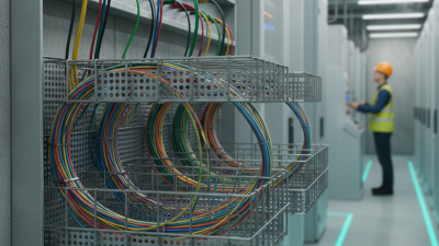
Start with the actual route, not just the tray drawing. A humid plant, coastal site, or washdown area can expose aluminum to moisture, salt, and cleaning chemicals. Check nearby metals too: direct contact with dissimilar metals may accelerate corrosion, so suitable separation or isolation may be needed. In dusty or hot areas, consider buildup, ventilation, and access for inspection. Small details matter.

Support design must account for cable weight, tray weight, span, and expected loads during installation. NEMA VE 2, Cable Tray Installation Guidelines, advises using the tray’s loading information and specified support arrangement; do not assume one span fits every route. IEC 61537 also assesses tray systems under defined loading and span conditions. Check the supporting structure, anchors, and local vibration, not only the tray rails. A strong tray on a weak wall is still a problem.

Temperature movement deserves attention on long runs. The Aluminum Association’s Aluminum Design Manual gives aluminum a thermal expansion coefficient of about 23.2 micrometres per metre per °C. A 30-metre run across a 50°C temperature change could therefore shift about 35 millimetres. Allow for movement at joints and follow the system’s installation guidance. I would recheck this calculation against site temperatures; neat drawings often miss the real exposure.

How to Choose the Right Aluminum Cable Tray: Assess the Installation Environment and Support Conditions

Material density affects tray dead load and should be considered when evaluating support requirements.

Installation note: Aluminum has an approximate density of 2,700 kg/m³, compared with about 7,850 kg/m³ for carbon steel. Actual tray weight depends on its design and dimensions. Check the selected system’s load tables and specified support spans, and account for cable loads, corrosion exposure, temperature changes, and other site conditions.

Match Tray Type and Dimensions to Cable Requirements

Choosing an aluminum cable tray starts with cable type, quantity, and installation conditions. Ladder trays suit larger power cables that need airflow and frequent access. Solid-bottom trays offer more support for small or sensitive cables, but can retain heat. Perforated trays sit between these options. They provide support while allowing some ventilation. Consider the route, too: tight bends, vertical runs, and future branches affect fitting choices.

Size the tray using actual cable outside diameters, not nominal conductor sizes. Allow space for separation, pulling, and planned additions; a tray packed tightly today can become difficult to inspect tomorrow. The Aluminum Association lists aluminum’s density at about 2.70 g/cm³, compared with about 7.85 g/cm³ for steel. That lower weight can ease handling, but it does not determine safe loading. NEMA VE 1 rates tray systems by load and support span, so check the applicable rating against cable weight and support spacing.

There is no universal fill percentage for every installation. Follow applicable electrical requirements and the cable manufacturer’s bend-radius limits. Measure the heaviest cable bundle, then verify the tray width, side-rail height, fittings, and supports as one system. A few extra centimeters may help with installation, though oversized trays can waste space. I have seen neat drawings underestimate elbow clearance. Check the route on site before ordering.

Check Load Capacity, Material, Finish, and Standards

Choosing an aluminum cable tray starts with the actual load, not the empty tray’s appearance. Add cable weight, expected future circuits, and any concentrated loads; then check the manufacturer’s load tables for your support spacing and allowable deflection. NEMA VE 1 and IEC 61537 provide relevant requirements for metal cable-tray systems, but confirm which standard applies to the project. A tray spanning 3 metres may perform very differently from the same model supported every 1.5 metres. Small spacing changes matter.

Material and finish should match the environment. Aluminum offers low weight and corrosion resistance, but salt spray, chemicals, and contact with dissimilar metals can still create problems. Choose a finish suited to the exposure, and check compatibility at fittings and fasteners. The International Aluminium Institute reports that recycling aluminum uses about 5% of the energy required for primary production, a useful consideration when material recovery matters. For a damp plant room, I would inspect joints and cut edges too; specifying a finish alone can feel reassuring, but it does not replace checking the whole installation. Compare documentation, load ratings, and test conditions before selecting a tray.

Choose Compatible Accessories and Confirm Installation Fit

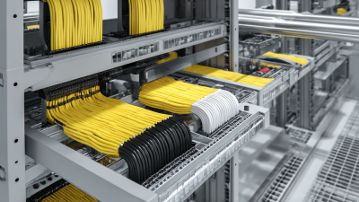
A cable tray is only as dependable as its connections. Match splices, elbows, reducers, covers, and hold-down clamps to the tray’s material, width, side-rail height, and rung spacing. A fitting that almost matches can leave sharp edges or a gap where cables catch. Small details matter. For aluminum systems, confirm that accessory metals and protective finishes suit the installation environment. Where dissimilar metals meet, check the project’s corrosion-control requirements and use specified isolation components.

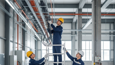
Confirm the route on site before ordering. Measure clearances around beams, pipes, and equipment, then check bend radius against the cable manufacturers’ requirements. The Aluminum Association’s Aluminum Design Manual lists aluminum density at about 2.7 g/cm³, compared with roughly 7.85 g/cm³ for steel; lower tray weight can ease support demands, but it does not determine allowable cable load. Verify the selected tray-and-accessory assembly against its rated load and span. NEMA VE 1 covers cable tray system requirements, while NEMA VE 2 provides installation guidance. Check twice. I’d still revisit the layout after the first support locations are marked; drawings can miss a stubborn obstruction. Ensure bonding hardware, expansion connections, and covers are compatible and accessible for inspection.

How to Choose the Right Aluminum Cable Tray - Choose Compatible Accessories and Confirm Installation Fit
Selection Dimension What to Confirm Accessory or Fit Check Why It Matters
Tray style Choose ladder, ventilated-bottom, or solid-bottom tray based on cable support, ventilation, and environmental needs. Check that fittings, covers, and hold-down hardware are designed for the selected tray style. Accessory shapes and attachment points can differ between tray constructions.
Width and side-rail height Measure the tray’s nominal width and side-rail height, then compare them with the required cable space and route. Match splice plates, reducers, covers, and fittings to the tray dimensions and profile. A dimension mismatch can prevent secure connections or leave cables inadequately protected.
Load and support span Estimate the cable load and confirm the tray’s allowable load at the planned support spacing using the manufacturer’s load data. Use compatible supports and connectors; verify their ratings and recommended spacing. Tray capacity depends on the tray design, load, and distance between supports.
Route changes Plan horizontal bends, vertical bends, tees, crosses, and reducers before installation. Confirm each fitting matches the tray width, side-rail profile, and required bend direction and radius. Correct fittings help maintain cable support and avoid abrupt changes in the cable path.
Splice connections Check the connection method and the location of joints relative to supports, as specified by the tray system instructions. Select splice plates and fasteners made for the same tray profile; use expansion splice hardware where movement is required. Properly matched connections help preserve mechanical continuity and accommodate intended movement.
Thermal movement Consider temperature range, run length, and installation conditions when determining whether expansion provisions are needed. Use the specified expansion connectors and bonding provisions, and follow the system instructions for placement and gaps. Aluminum expands and contracts with temperature changes; the connection design must allow for movement where required.
Covers and retainers Decide whether cables need a cover or additional retention based on the location and installation requirements. Match cover width and attachment style to the tray; check that clamps or hold-downs fit the rails and do not obstruct cables. Compatible covers and retainers stay secure and fit without interfering with the cable arrangement.
Cable bend radius and fill Check cable manufacturers’ minimum bend-radius requirements and applicable electrical-code limits for tray fill. Choose fitting radii and tray width that provide adequate space for the installed cables. Insufficient space or tight bends can damage cables and make installation or maintenance difficult.
Bonding and electrical continuity Determine bonding and grounding requirements from the project design and applicable electrical codes. Use the specified bonding jumpers or listed connection hardware across joints where required; do not assume a mechanical joint provides the required continuity. Electrical continuity requirements depend on the installation and must be verified rather than assumed.
Site conditions and clearance Check exposure to moisture, chemicals, temperature, and nearby equipment, as well as access for installation and future maintenance. Confirm the aluminum tray and accessory materials or finishes are suitable for the environment and that the assembled route clears nearby services. Environmental suitability and adequate clearance help prevent premature deterioration and installation conflicts.

Exclusive Access

Unlimited Resources

Detailed information on our products to assist you with the planning of your cable management project

Register Now

BIM Files

Step Files

Installation Manuals

User Guides

Best Practice Guides

Technical Charts