Why Do You Need an Electrical Test Kit?
Electrical problems are often invisible until a breaker trips, equipment overheats, or a connection fails. The risk is not merely theoretical. NFPA’s 2021 report, Home Fires Involving Electrical Distribution and Lighting Equipment, estimated an average of 32,620 U.S. home fires involving this equipment each year from 2015 to 2019. These fires caused an estimated 425 civilian deaths annually. A test instrument cannot prevent every incident, but it can help reveal conditions that deserve attention.
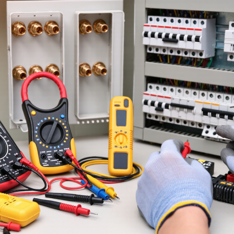
An Electrical Test Kit gives electricians and maintenance staff practical tools for checking circuits and equipment. Depending on its contents, it may include a digital multimeter, voltage tester, test leads, and accessories. These tools can measure voltage, check continuity, and help identify unexpected readings before repairs proceed. Small details matter: a damaged lead, an unsuitable measurement range, or the wrong instrument rating can undermine a test. A screen showing zero is not, by itself, proof that equipment is safe to handle.
That distinction matters. A lot.
Choosing a kit means matching its ratings and functions to the work, then following the manufacturer’s instructions and established safety procedures. Qualified users should verify the instrument works before and after checking for a hazardous voltage. This step is easy to overlook when a job feels routine. A kit is useful, but it does not replace training, sound judgment, or appropriate protective equipment. It can also create false confidence if users treat every reading as definitive. Used carefully, however, it helps turn guesswork into documented checks—and gives technicians clearer evidence when deciding what needs further investigation.
What Electrical Test Kits Measure: Voltage, Current, Resistance, and Continuity
An electrical test kit helps turn an uncertain fault into measurable information. Voltage shows the electrical potential between two points, such as across a battery or an outlet. A reading that differs from the expected value can point to a supply problem, but it does not explain the cause by itself. Context matters.
Current measures how much electrical flow passes through a circuit. A meter usually measures it in series, so the circuit must be opened and the meter connected correctly. This is easy to get wrong. Resistance describes how strongly a component opposes current, and it should be checked only when power is off and the component is safely isolated. Continuity testing checks whether a path is complete. A beep can help locate a broken wire, loose connection, or open fuse, but it cannot prove that a circuit is safe to use.
Good measurements depend on choosing the right setting and test points. Check the kit’s ratings and leads before testing, and never rely on a single reading to make a safety decision. I still find continuity results deceptively reassuring: a path may beep while a connection remains poor under load. For unfamiliar or high-voltage work, stop and ask a qualified electrician.
Why Do You Need an Electrical Test Kit? - What Electrical Test Kits Measure: Voltage, Current, Resistance, and Continuity
| Measurement | What It Measures | Unit | Illustrative Reading | Typical Use and Important Note |
| AC voltage | Electrical potential between two points in an alternating-current circuit. | Volts (V) | About 120 V or 230 V at a nominal household supply, depending on the region. | Used to check AC supplies and outlets. Actual readings vary with location and conditions; use equipment rated for the circuit. |
| DC voltage | Electrical potential in a direct-current circuit, with fixed polarity. | Volts (V) | Approximately 1.5 V for a nominal single-cell alkaline battery; approximately 12 V for a nominal 12 V battery system. | Useful for checking batteries and DC power supplies. Battery voltage changes with charge, load, and battery chemistry. |
| AC current | The rate of charge flow in an alternating-current circuit. | Amperes (A) | 0.25 A (example load current) | A standard multimeter measures current when connected in series; a suitable clamp meter can measure current around a conductor. Check the instrument’s current and safety ratings. |
| DC current | The rate of charge flow in a direct-current circuit. | Amperes (A) or milliamperes (mA) | 0.50 A (example load current) | Used to check current drawn by DC devices. Connect in series and use the correct input jack; never place a meter set to current directly across a voltage source. |
| Resistance | Opposition to electric current in a component or circuit path. | Ohms (Ω), kilohms (kΩ) | 220 Ω (example resistor value) | Useful for checking resistors and locating open or high-resistance paths. Switch off power and discharge relevant capacitors before measuring resistance. |
| Continuity | Whether a conductive path exists between two points, usually indicated by a tone or display. | Pass/fail indication; resistance may also be displayed in Ω | A low-resistance path may trigger a tone; the threshold depends on the instrument. | Used to check wires, fuses, and connections. Test only on de-energized circuits; a continuity tone does not prove a circuit can safely carry its rated current. |
Readings above are illustrative, not acceptance limits. Available functions, measurement ranges, and safety ratings vary by test instrument. Follow the instrument’s instructions and applicable electrical-safety procedures.
How to Choose CAT III 600 V or CAT IV 300 V Meters Under IEC 61010
Why Do You Need an Electrical Test Kit? How to Choose CAT III 600 V or CAT IV 300 V Meters Under IEC 61010
Choose a meter by the circuit’s location and transient risk, not voltage alone. CAT IV applies near the installation origin, such as a service entrance; CAT III covers distribution circuits, including building panels and fixed wiring. IEC 61010-1, Annex K, lists impulse withstand levels of 4 kV for CAT IV 300 V and 6 kV for CAT III 600 V. These figures describe different category-and-voltage combinations. They do not make the ratings interchangeable. The label can feel counterintuitive: the lower-voltage CAT IV meter is designed for a more severe measurement environment.
Check the meter’s complete marking, including voltage-to-earth rating, probe ratings, and measurement instructions. A CAT III 600 V meter may suit a distribution panel, while a CAT IV 300 V meter may be appropriate at the service origin. If the work spans both locations, select equipment rated for the highest category and voltage involved. Don’t guess.
Tips: Match the meter and leads as a set. Inspect insulation and probe guards before use; a damaged lead can undermine an otherwise suitable rating. When the circuit location is unclear, pause and verify it against the site’s electrical documentation and IEC 61010 guidance.
How OSHA 1910.333 Requires Testing Circuits to Confirm They Are De-Energized
Why Do You Need an Electrical Test Kit?
How OSHA 1910.333 Requires Testing Circuits to Confirm They Are De-Energized
OSHA 1910.333 requires a qualified person to verify that exposed circuit parts are de-energized before work begins. A switch position or control display is not proof. Under the rule, workers must treat parts as energized unless they are properly de-energized and locked or tagged. ESFI’s analysis of U.S. Bureau of Labor Statistics data recorded 126 workplace deaths from electrical exposure in 2022. The figure makes verification more than a paperwork step.
A suitable electrical test kit helps check for voltage at the exact conductors and terminals where work will occur. Test each relevant circuit element, and consider possible induced voltage or backfeed from another source. Use an appropriately rated tester and leads, and inspect them for cracks, exposed wire, or damaged insulation. A meter can give a false sense of certainty if its battery is weak or its leads are faulty. Verify the tester on a known live source before and after checking the circuit; this confirms the instrument worked during the test.
Tips: Isolate every energy source. Test phase-to-phase and phase-to-ground where applicable. Keep hands clear of exposed metal. Record what you checked. Small details matter. Even a careful routine can be rushed, so pause if the readings or circuit labels do not make sense.
Which Insulation-Test Voltages IEC 60364-6 Specifies: 250, 500, and 1,000 V DC
Why Do You Need an Electrical Test Kit?
Which Insulation-Test Voltages IEC 60364-6 Specifies: 250, 500, and 1,000 V DC
IEC 60364-6 links insulation-test voltage to the circuit being tested. For SELV and PELV circuits, it specifies 250 V DC and a minimum insulation resistance of 0.5 MΩ. Circuits up to and including 500 V, including FELV, require 500 V DC and at least 1 MΩ. Circuits above 500 V require 1,000 V DC, with the same 1 MΩ minimum. Check the applicable edition and installation conditions before testing; connected electronics or surge-protection devices may need to be handled carefully.
The right voltage matters. A test that is too high can damage connected equipment, while a low reading may point to deteriorated insulation, moisture, or a wiring fault. Electrical Safety Foundation International, drawing on NFPA data, reports about 51,000 home electrical fires annually in the United States, with roughly 500 deaths and 1,400 injuries. Insulation testing cannot prevent every fire, but it can reveal some faults before energizing. On site, note the selected voltage, isolate sensitive loads, and allow for stored charge after testing. Small detail. It matters. A clean reading is useful, not a complete diagnosis.
Why Do You Need an Electrical Test Kit?
IEC 60364-6 specifies insulation-test voltages according to the circuit category. An insulation tester helps verify that the measured insulation resistance meets the applicable minimum.
- SELV and PELV circuits: 250 V DC test voltage; minimum insulation resistance 0.5 MΩ.
- Circuits up to and including 500 V, excluding SELV and PELV: 500 V DC; minimum 1 MΩ.
- Circuits above 500 V: 1,000 V DC; minimum 1 MΩ.
Disconnect or protect equipment that could be affected by the test, and follow the applicable standard edition and local requirements.
How to Check Test Leads and Verify Meter Operation Before and After Testing
A meter is only as trustworthy as its leads and its last function check. Before testing, inspect each lead from plug to probe tip. Look for cracked insulation, bent metal, loose connections, or damaged finger guards. Flex the cable gently near the strain relief; hidden breaks can be easy to miss. Check that the leads match the meter’s rating and the measurement you plan to make. Small details matter.
NFPA 70E’s 2024 electrical-safety standard calls for verifying an instrument on a known source before and after testing for absence of voltage. That check helps reveal a failed meter or depleted battery. Use the correct function and range, then confirm the meter responds to the known source. Test the circuit, and repeat the known-source check immediately afterward.
The U.S. Bureau of Labor Statistics’ 2022 Census of Fatal Occupational Injuries recorded 145 fatal work injuries involving exposure to electricity. That figure cannot measure every testing error, but it gives the stakes context.
A rushed check can feel redundant. It isn’t. Record damaged leads, remove them from service, and don’t assume yesterday’s successful check proves today’s meter is working.


