Blog
How to Choose the Right Cable Tray in 2026
Choosing a cable tray in 2026 is no longer a simple sizing exercise. Data centers, factories, and commercial buildings are adding more power and network cabling, often in tight ceiling spaces. The International Energy Agency’s Electricity 2024 report projects that global data-center electricity use could exceed 1,000 terawatt-hours by 2026. That growth makes capacity, access, and future expansion practical design concerns—not details to leave until installation day.
Electrical educator Mike Holt’s guidance offers a useful reminder: code compliance is a baseline, not a substitute for sound design. A tray that fits today’s cable bundle may leave little room for a new circuit, a sharp turn, or a technician’s hands. Small details matter. Before selecting a system, compare cable weight and fill, span lengths, support points, corrosion exposure, and available space. Steel, aluminum, and nonmetallic options each bring trade-offs; the right choice depends on the site and the load.
This guide examines those decisions, from ladder and solid-bottom styles to material, sizing, and installation planning. It also considers maintenance and expansion, since a tray is difficult to change once it disappears above a finished ceiling. Specifications help, but they cannot replace a site walk. Measure the route. Check the supports. And be honest about what remains uncertain—early project drawings are not always the final installation.
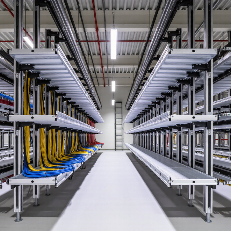
Understanding Cable Tray Functions and System Requirements
Cable tray is a support system, not simply a route for cables. It carries cable weight, keeps runs organized, and can make inspection or future changes easier. The right choice depends on cable type, quantity, environment, and access needs. Space matters. A tray packed tightly may limit cooling and leave little room for later additions.
NEMA VE 1-2017 sets out load classes in pounds per foot and relates them to support spans. That distinction matters: a calculated cable load of 12 lb/ft does not, by itself, prove a tray is suitable. Check the tray’s rated capacity at the planned span, and account for fittings, concentrated loads, and possible future cables.
The NEMA/NECA 101 installation standard also addresses support, bonding, and installation practices. Heat matters too. A tidy drawing can still miss the weight of a field-added cable bundle.
System requirements shape the tray style. Ladder trays suit many power runs and can help dissipate heat; solid-bottom designs may better protect sensitive cables from falling debris. Separate power and communication runs where project specifications or applicable electrical rules require it. For outdoor locations, consider corrosion exposure, standing water, and temperature changes.
Not just weight. I would revisit the cable schedule before ordering: early estimates are often incomplete, and that uncertainty should be stated rather than hidden.

Assessing Cable Loads and Installation Conditions
How to Choose the Right Cable Tray in 2026
Assessing Cable Loads and Installation Conditions
Start with the cables, not the tray dimensions. List each cable type, its weight per metre, and the number planned for the route. Include likely additions, but avoid sizing around guesses alone. A tray that looks spacious can still exceed its rated load. Check the tray’s load tables against the actual support span, and account for heavier sections near junctions or equipment. Keep bend radius and cable separation in mind, too. Small details matter.
Next, inspect the installation conditions. An indoor ceiling route faces different demands from an outdoor run exposed to rain, temperature changes, or corrosive air. Note the mounting surface, available clearance, access for maintenance, and positions of bends and drops. Measure the route on site where possible. Drawings can be outdated. Confirm that supports, fittings, and expansion points suit the chosen tray and local conditions. If loads or structure are uncertain, have a qualified professional review the design.
Tips: Record cable weights and support spacing before ordering. Leave practical room for future work, but verify the added load. Recheck the plan after a site walk; one missed obstruction can change the route.
Comparing Tray Types, Materials, and Support Options
How to Choose the Right Cable Tray in 2026
Comparing Tray Types, Materials, and Support Options
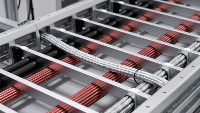
Ladder tray suits long runs of power cable, where open sides aid airflow and inspection. Perforated tray offers more continuous support for smaller cables. Solid-bottom tray helps shield sensitive wiring from falling dust, but it retains more heat. NEMA VE 1 provides load-and-span ratings for metal tray systems; compare ratings at the intended support spacing, not just tray width. A wider tray is not automatically stronger.
Material changes weight, corrosion resistance, and installation effort. NIST reference data lists aluminum density at about 2.70 g/cm³, versus 7.87 g/cm³ for iron; actual steel products vary. Aluminum can reduce the weight carried by building supports, while coated or stainless steel may suit harsher environments. There is no universal winner. Check the local exposure, cable load, and connection hardware. NEMA VE 2 installation guidance also emphasizes proper supports and fittings.
One detail is easy to underestimate: a small spacing change can affect the load a tray safely carries.
Tips: Check the manufacturer’s load table for the exact span and tray configuration. Include cable weight, future additions, and concentrated loads. Then confirm support type—trapeze, wall bracket, or floor stand—fits the route and structure. Allow room for bends and access. Measure twice.
Sizing Cable Trays and Planning Routes
Sizing starts with the cables, not the tray catalog. List each cable’s outside diameter, quantity, weight, and likely future additions. The 2023 National Electrical Code, Article 392, sets cable-tray fill limits according to cable type and size; there is no universal fill percentage for every installation. For a preliminary layout, a 300 mm-wide tray with a planned 50 mm cable depth offers 15,000 mm² of gross area. Apply the relevant code limit, then verify the actual cable arrangement. Check the load rating and support span against IEC 61537, which tests tray systems under defined loading conditions.
Plan routes around real obstacles: beams, pipes, equipment doors, and tight turns. NEMA VE 2 installation guidance covers cable-tray installation, including support and routing considerations. Keep bends gentle enough for each cable’s minimum bend radius, and leave access for pulling and inspection. Small detail. A route that clears a drawing may still block a technician’s hands.
Allow space for future circuits, but avoid oversized trays that invite loose, undocumented routing. Mark elevations and crossings on the layout, then walk the proposed path with installers before fixing supports. A common planning miss is counting cable area while overlooking separation needs, entry points, or the extra slack required at equipment. Recheck those details after cable selections are final; early estimates are useful, and sometimes wrong.
How to Choose the Right Cable Tray in 2026: Sizing and Route Planning
Illustrative cable-fill comparison for a 50 mm-deep tray carrying a cable bundle with an estimated combined cross-sectional area of 90 cm².
The percentages are calculated as cable bundle area divided by the tray’s nominal width-by-depth area. A 40% fill is shown as an example planning target to leave room for future additions; it is not a universal code limit. Confirm cable arrangement, loading, applicable requirements, and manufacturer guidance before selecting a tray or finalizing a route.
Checking Standards, Safety, and Future Expansion
Before choosing a cable tray, check the standards that apply to the building, location, and cable type. Confirm the current requirements for materials, loading, support spacing, bonding, and separation from other services. A specification written for one environment may not suit a damp plant room or an outdoor rooftop. Verify details with the project engineer and the relevant authority, rather than relying on an old drawing.
Safety depends on installation as much as tray selection. Check the manufacturer’s load data against the expected cable weight, including future additions. Inspect supports, joints, and bends; a weak connection can matter more than a strong straight section. Keep sharp edges away from cable jackets, fit covers where exposure calls for them, and maintain required clearances. Small details matter. A tidy drawing can still be wrong once ducts, pipes, and access routes appear on site.
Plan for expansion before the tray is full. Leave practical spare capacity, and consider where future branches, pull points, and access space will fit. Oversizing every run can waste money and crowd the ceiling, though. Walk the route with installers when possible, then compare the plan with actual obstructions. Some assumptions will need revising. That is better than discovering later that one added circuit requires a costly reroute.
How to Choose the Right Cable Tray in 2026 - Checking Standards, Safety, and Future Expansion
| Tray option or decision area | Typical characteristics | Suitable applications | Safety and installation checks | Future expansion considerations |
|---|---|---|---|---|
| Ladder tray | Two side rails joined by regularly spaced rungs; open construction promotes ventilation and provides frequent cable-support points. | Many power and control cable routes, particularly where longer runs and accessible cable installation are needed. | Check the tray’s published load and deflection data for the actual support span, fittings, cable arrangement, and environmental conditions. Secure and support cables as required by the applicable electrical code. | Often practical for later cable additions, provided spare capacity, access space, bend radii, and support capacity are planned. |
| Ventilated trough tray | A bottom with openings and raised sides; offers more continuous cable support than ladder tray while allowing some airflow. | Control, instrumentation, and smaller cable runs where distributed support is useful. | Confirm opening size and cable-support requirements, and check that the installation suits the site’s dust, moisture, and cleaning conditions. | Can accommodate additional cables if the tray’s fill, heat, loading, and access limits remain acceptable. |
| Solid-bottom tray | Continuous bottom and side rails provide a more enclosed support surface; covers may be available as part of a compatible system. | Routes where cable support or protection from falling debris is a priority, subject to project and code requirements. | Assess ventilation and cable ampacity, drainage and condensation risks, cover requirements, bonding, and access for inspection. | Plan access and spare space carefully; adding cables later may be less convenient than in an open tray. |
| Wire-mesh tray | Open mesh construction is lightweight and can be cut or shaped using approved installation methods. | Many data, communications, and light-duty control cable routes; suitability depends on the system’s rated capacity and cable requirements. | Use the system’s specified supports, fittings, and edge protection. Check cable bend radius, support spacing, cut-edge treatment, and bonding requirements. | Its open construction can simplify access, but confirm that added cables will not exceed load, fill, or separation requirements. |
| Channel tray | A compact tray format generally used for smaller cable groups; available in different materials and configurations. | Short routes, small cable bundles, and localized equipment connections where the selected system is appropriately rated. | Verify capacity, support intervals, fittings, and cable protection for the specific installation; do not assume a small tray is suitable for power cables. | Allow room for additional circuits or provide a separate route if the channel has limited spare capacity. |
| Standards and jurisdiction | Common references include IEC 61537 for cable tray and cable ladder systems, NEMA VE 1 for metal cable tray systems, and NEMA VE 2 for installation guidance. | Use the standards and electrical code adopted for the project location. In the United States, NFPA 70 (NEC), including Article 392, addresses cable tray installations. | Confirm the locally adopted edition, project specifications, product qualification, grounding and bonding rules, cable-use restrictions, and inspection requirements with the responsible engineer or authority. | Document the design basis and keep spare capacity consistent with the applicable code and project requirements. |
| Material and corrosion protection | Options may include steel with a specified protective finish, stainless steel, or nonmetallic materials. Suitability depends on the system and environment. | Select for indoor or outdoor exposure, humidity, chemicals, salt, washdown, temperature, and structural requirements. | Check corrosion compatibility, finish damage and repair procedures, dissimilar-metal contact, and bonding continuity where applicable. | Choose a material and finish compatible with the expected service life and planned additions, rather than relying on appearance alone. |
| Capacity, loading, and support span | Capacity depends on tray construction, width and depth, material, support spacing, fittings, loading, and installation conditions; there is no single load rating that applies to every tray. | All installations, especially routes carrying heavy cables or spanning between structural supports. | Use the selected system’s load tables and engineering requirements. Include cable weight, concentrated loads where applicable, environmental loads, and installation conditions. | Reserve capacity only after checking both electrical fill and structural loading; planned spare space does not automatically mean spare load capacity. |
| Route planning and separation | Route layout affects cable bending, access, support locations, and separation between different cable classes. | Projects with power, control, instrumentation, or communications cables sharing congested spaces. | Follow applicable separation and segregation requirements. Check bend radius, pull access, egress and service clearances, penetrations, fire-stopping, and protection from physical damage. | Map likely future circuits, reserve route space, and avoid blocking access to equipment or other building services. |
Note: Requirements vary by jurisdiction and project. Confirm current adopted standards, code provisions, and system-specific ratings before specifying or installing cable tray.
Exclusive Access
Unlimited Resources
Detailed information on our products to assist you with the planning of your cable management project
Register Now